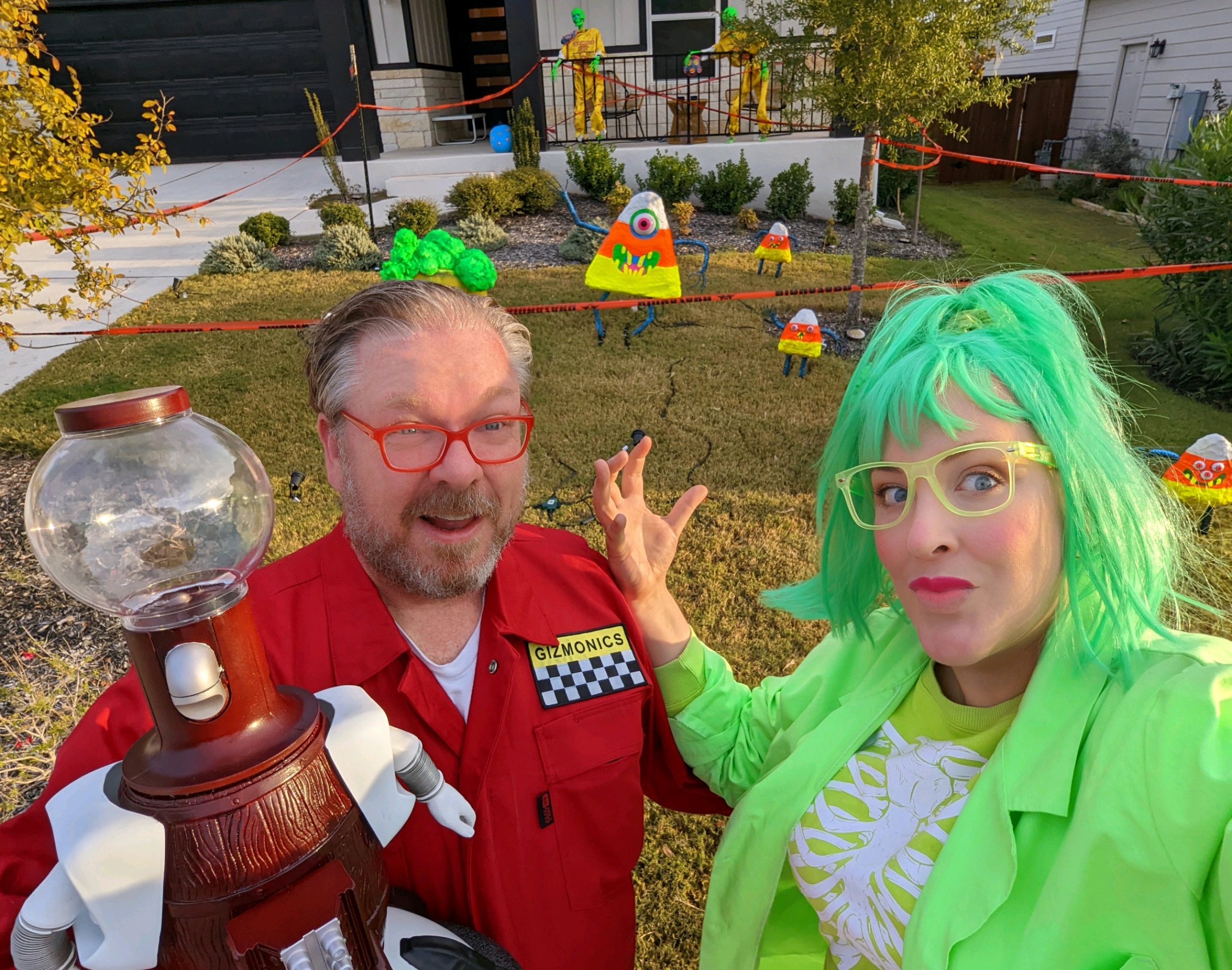
For my Halloween costume this year (2022), My wife and I decided to do a whole house theme. Early on, we decided to do something with Mystery Science Theater 3000. Not only do we love the show, but it (along with Futurama) was a show we both loved and had contributed to both of us staying sane during COVID lockdowns.
I'll cover some of our house decorations in a separate post, but Disney's Haunted Mansion highly influences our idea of a house decorated for Halloween. We don't want it to be that, but we want it to feel spooky and fun rather than scary. Creepy and fun are partially our sensibilities, but also because we have a lot of young children.
Yes, I'm A Nerd & An MST3K Fan
Let's talk about the costume with all that out of the way!
The central part of my costume was pretty easy to put together. I just purchased the items from this list (they're all readily available on Amazon, except for the Gizmonics patch found here)
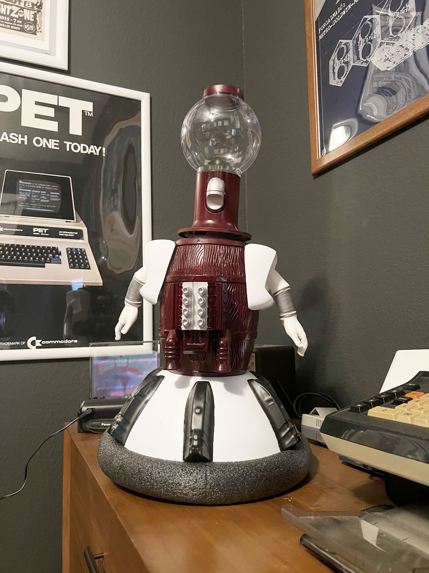
The best part of this costume was that it was an excuse to assemble a Tom Servo kit. There are two robots I've always wanted to build: replicas of Tom Servo and K9. K9 will happen someday, but I was able to do Tom Servo for this costume. Now, I've got a robotic buddy to serve as my rubber duck for debugging.
You may notice that his red color is not the original color. I ordered the matching color, but it took three months to arrive, so I used what I had. This color represents the colors I saw on my old tube television while watching MST3K when it aired.
Building a Servo, Tom Servo
I got the kit for Tom Servo here. It's a great kit and produces a screen-accurate version you can puppeteer. The instructions are unambiguous, but I got a little help from this excellent instructional video. It frames the instructional video part like an episode of MST3K. Genius!
Now, I didn't just want a puppet I could carry around. That would be awesome, but I wanted to take it to the next level. I wanted a puppet that I could also set up self-contained to play a selection of prerecorded Tom Servo clips!
The Animatronic Concept
So, I sat down and determined some objectives and specs for the project.
- I should still be able to use Tom Servo as a puppet in addition to some amount of animation.
- Tom Servo should be self-contained and powered by a battery pack.
- Use one of the multitude of Arduino Pro Minis I ended up with.
- The project should use one button to play a Tom Servo clip randomly.
- The project should have built-in speakers to play the sound files.
Some of the work around this, particularly the servos and Arduino code I would start with, were based on the eyeball pumpkins I made for the previous year - Halloween Fun 2021 - The Tiki-themed Mahalloween.
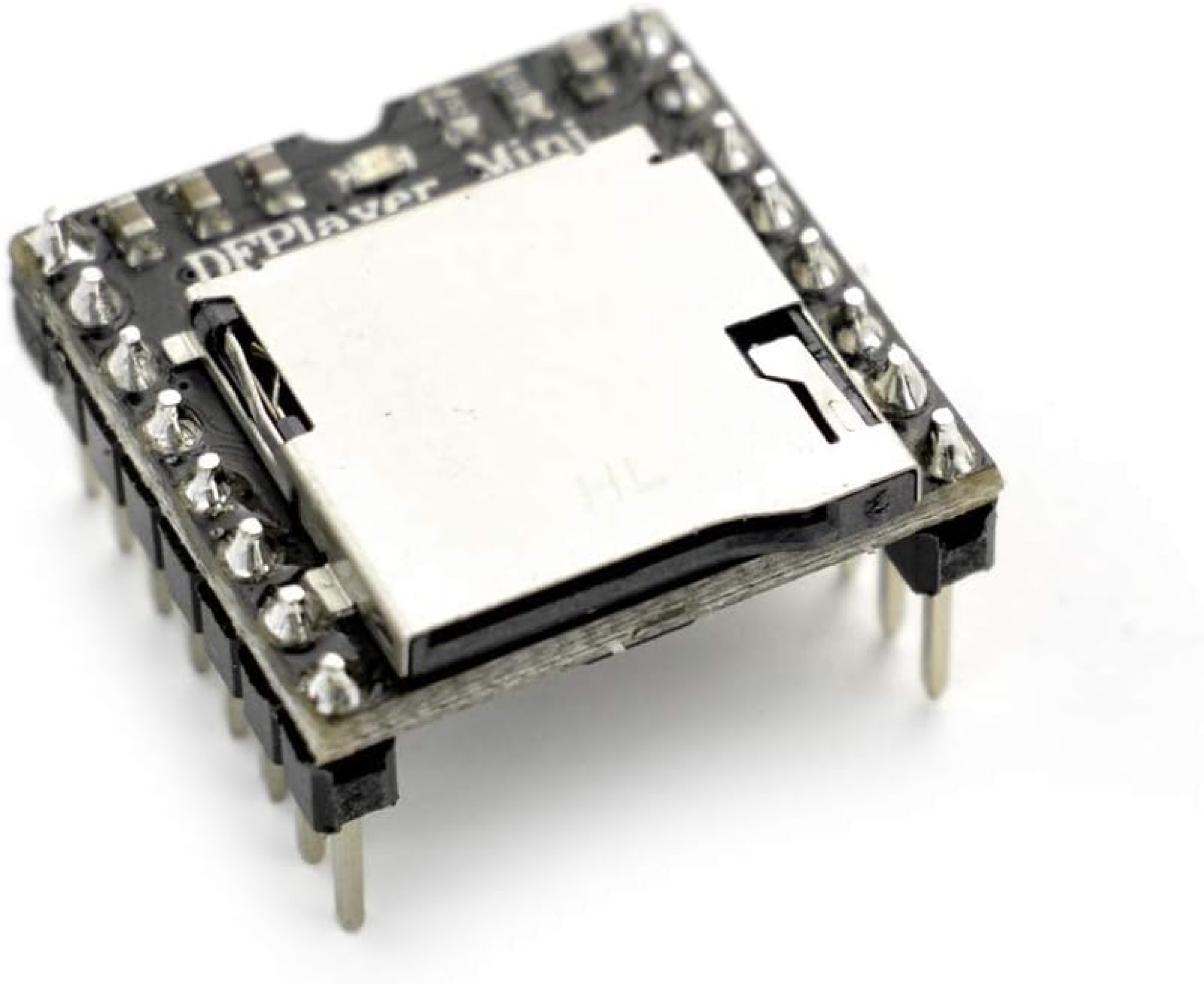
Additionally, I knew that I'd need some type of external mp3 player & simple amplifier setup since there was going to be no way to play mp3 files directly from the Arduino. That and there's only so much onboard storage on the Arduino Itself.
After a bit of research, I ran across this fantastic little board that also happened to have an Arduino Library, the DFPlayer Mini:
This little board seemed extraordinary. Additionally, I knew if I got in a pinch, it could be controlled by the Arduino via serial, so I could program something myself if needed. Here's an excellent little video on it.
Putting the Board Together
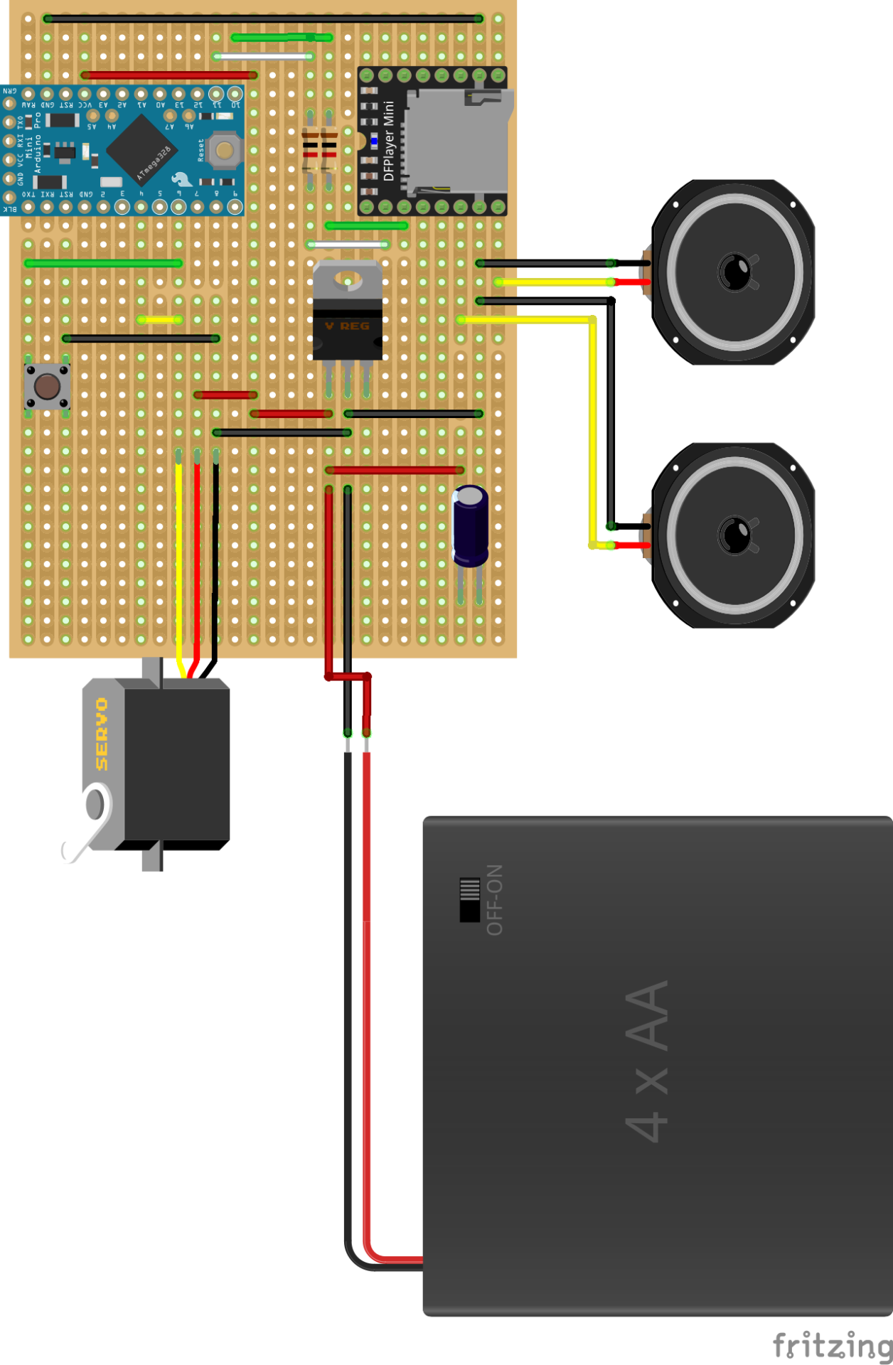
I could quickly source the rest of the parts I needed beyond the Arduino and DFPlayer Mini:
- Perf / Vero board - I had a bunch of these. I like to use these as they're simpler to work with than plain through-hole boards. With a little layout, you can use minimal wires and soldering to put these together. The main drawback is that your board may need to be more compact.
- Male and Female headers - already had.
- Capacitors - always have a bunch of these on hand.
- Resistors - yup, same as #3.
- Wires - I got too many.
- Tactile button - yeah, I got lots in lots of sizes.
- Battery holder - I ordered this from Amazon.
- Speakers - I ordered this from Amazon.
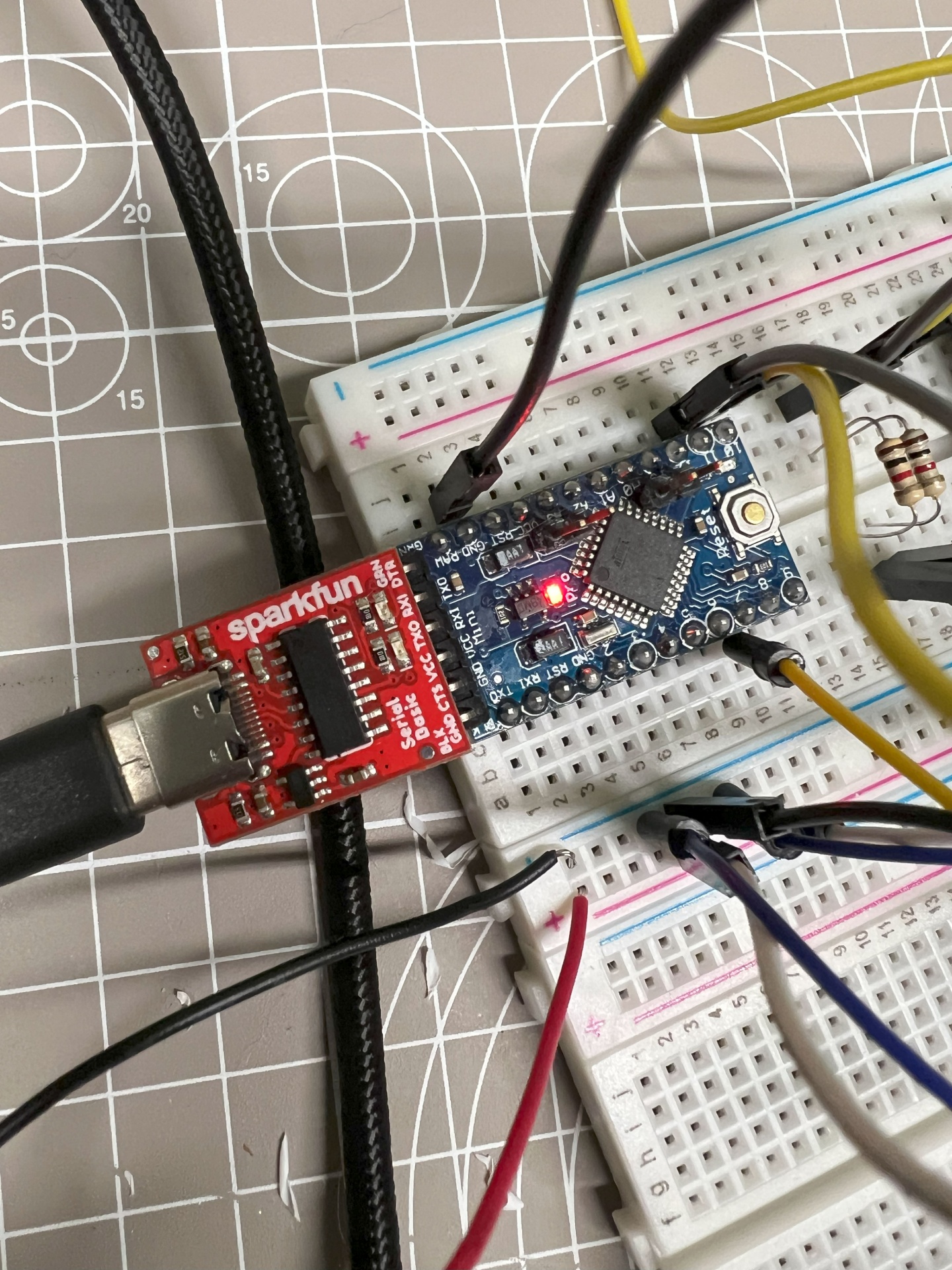
I had a general idea of what I was building and how I would go about it. I also had the information on what pins I would connect and how to power them. So, I created an initial version with all connections and boards on a breadboard to run some initial tests, like just triggering one track to play from the DFPlayer Mini on the board.
While most of the functionality worked as expected, I ran into a few issues with this layout that took some research online. While the DFPlayer Mini worked fine after a short period, around 5 minutes, it would start to have a pretty bad popping sound from the speakers. What was wrong? I did a bunch of research and found others with the same problem. Some recommendations included adding capacitors and resistors to help smooth the current. I tried these with varying success.
After further digging, I found a couple of reports that while the DFPlayer Mini is rated for between 3.3V to 5V, it likes a steady 3.3V. However, using 3.3V presented a little problem. I had a 5V Adruino and planned to have a common 5V rail and ground plane for everything. I did a minor redesign and added a little 3.3 voltage regulator. Adding the voltage regulator worked like a charm and proved that I'm still learning; I don't know what I'm doing! That's how I learn: by trying things and breaking or being willing to understand why something isn't working. I do know my limits, though, and I never would try to wing it with things that could blow up or cause serious harm.
Anyway, now I have my working prototype and can assemble the board.
Programming the Tom Servo
With the hardware at least partially resolved, it was time to start programming the Tom Servo. I used the Arduino IDE to program this as the programming would be relatively simple, and I would rely on Arduino libraries a lot: for the DFPlayer, for the Servo control, for the button and debounce.
I've put the code up into a public GitHub repository here. To approach the programming of the microcontroller, I broke the tasks down into a few different blocks as it's easier to work each part of the problem before gluing it all together into the overall main program.
So this program broke down into three main parts:
- Respond to the button click and select a random number from within the count of audio clips.
- Take the random number and select that number to play from the SD card of the DFPlayer Mini.
- Use that random number to pull up the array representing the keyframes (mouth open and mouth closed) that sync to the playing track.
It's important to remember that the DFPlayer will play its audio on its hardware while the Arduino handles the timing of the keyframes. While this doesn't mean anything in practice with this project, there could be a drift between the audio playing and the keyframes.
#1 Responding to the button click
This part was pretty straightforward:
void handleEvent(AceButton* /*button*/, uint8_t eventType, uint8_t /*buttonState*/) {
  // get a random number to play
  switch (eventType) {
    case AceButton::kEventPressed:
      randNumber = random(21);
      // cancel all servo timers
      timer.cancel();
      playQuote(randNumber);
      break;
  }
}
I chose to use AceButton as its API was easy to use and offered the button states and functionality I wanted, particularly debounce. Also, I didn't need to custom-code this.
This function handles the button click when pressed and selects a random number in the range of sound clips I have defined. The range is static.
Next up, we'll cancel all timers related to the servos. In the next block, we'll get into more detail on the animation function.
Finally, we'll call the playQuote function with the random number we generated earlier.
#2 Setting up the animation
// play audio and sync servos
void playQuote(byte clip) {
  //grab the array related to the item on display
  for (int i = 0; i < rows; i++) {
    animationCol1 = pgm_read_word_near(animations[clip][i]+0);
    animationCol2 = pgm_read_word_near(animations[clip][i]+1);
    if(animationCol1 != 0){
      timer.in(animationCol1, moveServo, animationCol2);
    }
  }
  myDFPlayer.play(clip+1);  //Play the selected mp3
}
Now, we get to the real meat of this. This function loads up the keyframes for the specific clip, sets up a bunch of timers for each animation keyframe, and then triggers the DFPlayer to play the audio clip. Let's walk through this!
First, you'll notice that we're going to loop through something called rows. What is this? We've predefined our clips and animations in a multidimensional array in the file audiosync.h. Here's a sample of that file to get an idea.
#ifndef AUDIOSYNC_h
#define AUDIOSYNC_hs
#include <Arduino.h>
const PROGMEM int clips = 21;
const PROGMEM int rows = 71;
const PROGMEM int columns = 2;
const PROGMEM int animations[clips][ rows ][ columns ] = {
  {
    {20, 0},
    {60, 1},
    {120, 0},
    {160, 1},
    {200, 0},
    {400, 1},
    {460, 0},
    {500, 1},
    {560, 0},
    {600, 1},
    {920, 0},
    {960, 1},
    {1280, 0},
    {2260, 1},
    {2380, 0},
    {2460, 1},
    {2560, 0},
    {2640, 1},
    {2700, 0},
    {2740, 1},
    {2820, 0},
    {2860, 1},
    {2960, 0},
    {3020, 1},
    {3160, 0},
    {3220, 1},
    {3440, 0}
  }
}
This 3D array contains:
- The first level contains an array where the index correlates to a specific audio clip.
- The next level contains an array of each keyframe for that clip.
- Finally, we have an array that reflects the time and state of the servo at that time (0 for closed and 1 for open). The second entry reads that at 60 milliseconds, the servo that controls the mouth should be in the open state.
At the top of this file, we declare the array max sizes we'll need to store all these attributes, where we get the clip, row, and column counts. For our purposes, we don't care if some of the arrays are smaller than what we define.
Now, back to the function that is using these:
// play audio and sync servos
void playQuote(byte clip) {
  //grab the array related to the item on display
  for (int i = 0; i < rows; i++) {
    animationCol1 = pgm_read_word_near(animations[clip][i]+0);
    animationCol2 = pgm_read_word_near(animations[clip][i]+1);
    if(animationCol1 != 0){
      timer.in(animationCol1, moveServo, animationCol2);
    }
  }
  myDFPlayer.play(clip+1);  //Play the selected mp3
}
So, we will loop through the array referenced by the clip number we chose previously to set up our animation.
The first thing to notice is that we will extract two variables from the clip keyframes. First, we want to get the millisecond timing (animationCol1), and second, we get the servo state (AnimationCol2, which represents the open or closed mouth state). You may have noticed that we're using a method called pgm_read_word_near(). We use this because we're not reading this variable from the Arduino RAM but from the Arduino flash memory. I had to go this route because the animation keyframe array was too large for the Arduino's limited onboard RAM. Apparently, on newer Arduino boards, you can also set a variable as a const, and it will use this method. I have yet to try that with this code. For more information, see here.
The second thing to note here is what we're doing in this loop with the milliseconds, and the servo mouth state is setting some timers to run the moveServo function later. The function uses the arduino-timer library to set up some non-blocking timers for later. Using a timer is a concept familiar to anyone who's done this in JavaScript. It's pretty straightforward to use; essentially, we set up the timer with the time it should run, the callback to use, and the data to send the callback. In our use case, we set it in this line:
timer.in(animationCol1, moveServo, animationCol2);
When the Adruino hits the timer, it calls this function to determine what to send the servo:
bool moveServo(int argument) {
  if (argument == 0) {
    myServo.write(openDeg);
  } else {
    myServo.write(closedDeg);
  }
  return false; // to repeat the action - false to stop
}
The argument sent here is whether the mouth should be open or closed. We set the openDeg and closedDeg at the top of the Arduino sketch:
// Variables will change:
byte fileCount;
byte openDeg = 100;
byte closedDeg = 0;
byte randNumber;
int animationCol1;
int animationCol2;
One additional note on all variables within an Arduino sketch and for microcontrollers in general: they are resource-limited devices. While we may not worry about using extra bytes when we're building something for the web or our home computers, we have to be very aware of that in this context. Choosing appropriate variable types is very important, as a few bytes could be the difference between doing what we want or not being able to build and deploy to the microcontroller.
#3 Playing the MP3
The last thing we must do is trigger the DFPlayer Mini to play the file we want. Triggering the DFPlayer Mini is handled by a straightforward call using the DFPlayer library:
myDFPlayer.play(clip+1); //Play the selected mp3
Every time I set up one of these DFPlayer minis, there are little quirks with the file layout on the device. I only have a few tips for these quirks other than trying different ways of setting up the file layout and how you call the files. Additionally, I always buy in multiples. Depending on the source, you may get some that don't work.
And now we're done!
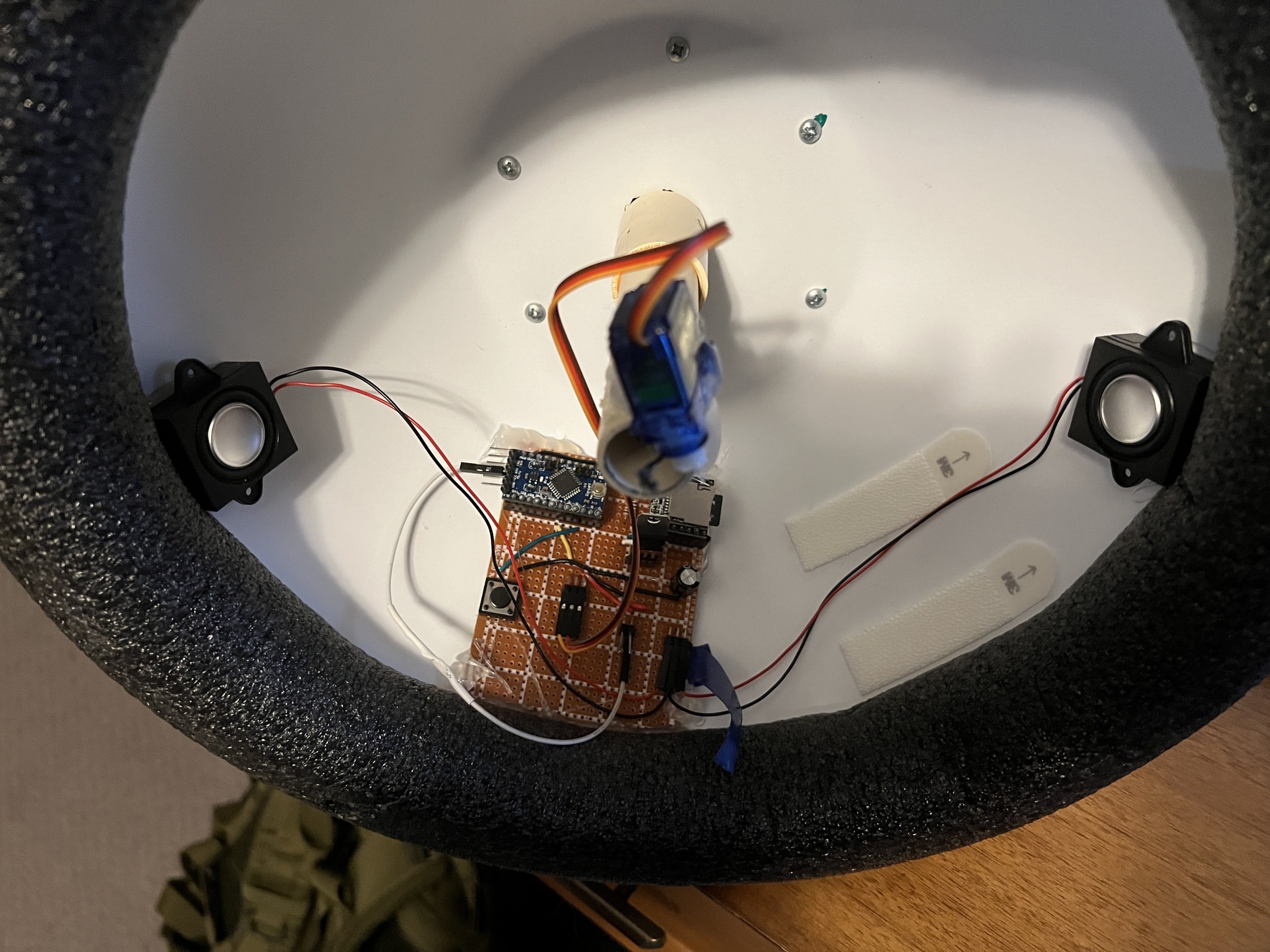
I ended up putting all the electronics in the hover skirt of the Tom Servo replica. I want to rework the button placement so it's a little easier to get to and rethink how I'm attaching the battery pack. It had fallen out multiple times and is not in this photo.
I'll be adding a video of the actual robot in action here at a later date.